Sustainable airliner designs of the future will need to be extremely quiet as well as ultra-efficient—a potentially contradictory combination, given some of the unconventional airframe propulsion configurations now under study.
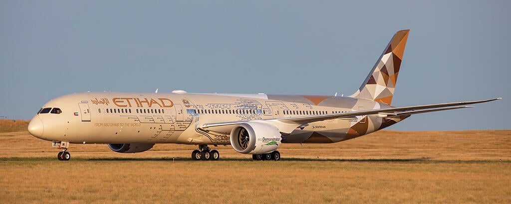
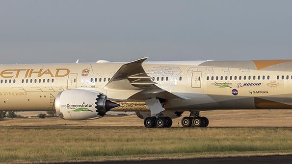
- 787-10 completed 88 noise tests in 20 flight hours
- The aircraft carried 214 noise sensors in four arrays
As NASA begins planning for one such shape—a future Transonic Truss-Braced Wing (TTBW) X-plane flight demonstrator—the agency aims to model the design of this and other advanced concepts using the most sophisticated noise-prediction code yet developed. Known as ANOPP, or the Aircraft Noise Prediction Program, the code will be a much-improved update of NASA’s long-running program, and it will call for incorporating the first vehicle-system-level acoustic data ever collected from a flight-test program.

The data, gathered with Boeing during the manufacturer’s recently completed 787-10 ecoDemonstrator test effort at Glasgow, Montana, represents several other firsts, according to Russell Thomas, NASA technical lead for the research agency’s Propulsion Airframe Aeroacoustics (PAA) and Aircraft System Noise flight test. Not only was it the first NASA flight test to study individual noise sources, their interaction with an airframe and how they combine to produce total aircraft noise, but he says it was also the agency’s first flight test aimed at measuring shielding and reflection PAA effects.
“This test was very different from the start because we set out our objectives to go after the system-level acoustic objectives in a systematic way,” Thomas says. “And it was also different in terms of the integration of the propulsion and the airframe, as well as the engine and aircraft components. Then [we did] it in this kind of comprehensive and systematic way in a single flight test. So, from NASA’s point of view, this is the first time we have done such a thing,” he adds.
The test effort, which amassed data from 88 aircraft test conditions flown over five days and 20 flight hours, marked a “significant effort to make major upgrades to ANOPP for the future,” says Thomas, who is also a senior research engineer at the Aeroacoustics Branch of NASA’s Langley Research Center.
“We already know we need to make improvements in the code for the types of technologies that are coming in the future such as higher-bypass-ratio fans, more effective [acoustic] liners and newer airframe designs,” explains Thomas. “This test gives us not just great flight-level data but also very high-resolution information that will allow us to evaluate and quantify deficiencies, but then also make improvements to it.”
The test program, which had been in planning for five years, was also a significant benefit to Boeing, says the company’s principal investigator, Michael Czech.
“We always look for ways of lowering aircraft noise, and the collaboration with NASA really allowed us to look at unique and new ideas that are a little bit outside the box,” Czech says. “That opens up additional acoustic design space for concepts that are distinctly quieter in the future, or that allows us to develop operational procedures that are a lot quieter than what we have right now.”
Based on NASA’s objectives, Boeing and the agency collaboratively developed requirements for instrumentation and planning for the test, which included “how we operated the airplane and performed some special maneuvers and the flightpaths we selected,” says Czech. “It was a highly unique setup, both from an instrumentation perspective as well as from the way we flew it. That provided the setting to check out these novel ideas and come up with new ways to reduce noise.”
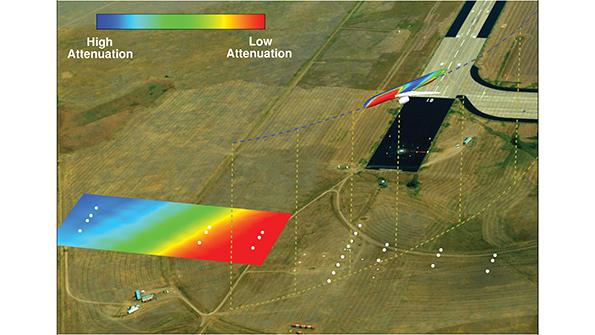
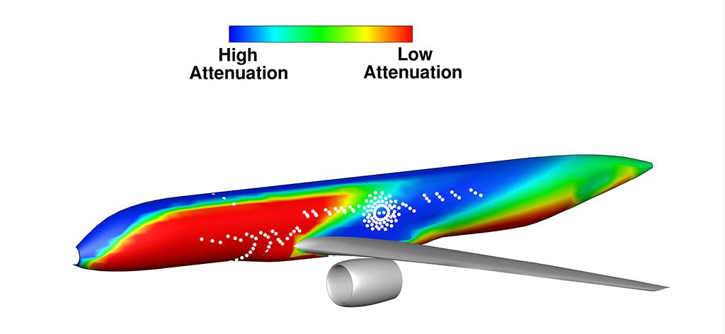
The program set out to accomplish several key propulsion airframe aeroacoustics test objectives, one of the most important of which was measuring the shielding and reflection effects of the airframe on full-scale engine fan noise. Other key test targets included measuring the direction of the aircraft’s sound field in azimuth and assessing the effect of covering over the acoustic lining in the aft duct of the engine.
Measuring azimuth angles was undertaken to improve understanding of the noise field around the aircraft and how it propagates to the surrounding ground below. Meanwhile, the liner test was designed to quantify the effectiveness of the acoustic treatment as well as to change the sound characteristics by increasing the dominance of the fan noise, thereby simulating the signature of future higher-bypass-ratio engines.
Sound was recorded using a sophisticated set of six different acoustic measurement systems located in various positions around the aircraft and on the ground. A total of 214 sensors were arranged in four sets on the 787, including phased arrays under the inboard wing-fuselage join and on the side of the fuselage above the wing. The suite was completed with a linear array along the fuselage and a circumferential microphone array around the fuselage mounted at two angles relative to the engine inlet.
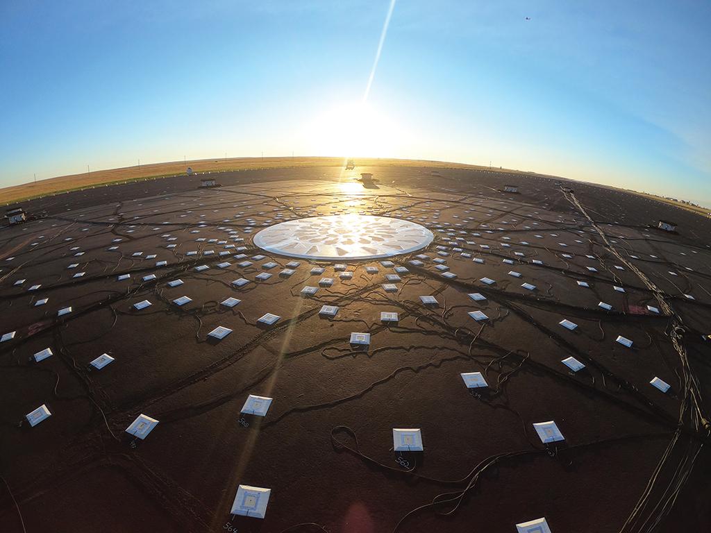
The ground instruments consisted of an array of 960 microphones placed in a 300-ft.-dia. spiral pattern across the end of the runway at Glasgow, a former U.S. Air Force Strategic Air Command base. A second “far field” array made up of 31 microphones was also laid out in a wider area beyond the runway. This was used to provide a range of directivity measurements of overall aircraft levels as well as the level of engine noise shielding by the fuselage.
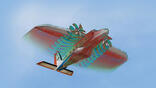
To obtain measurements of the shielding and reflection effects, as well as the azimuthal directivity of the sound field, the crew of the 787 banked the aircraft up to 35 deg. during climbout. The carefully rehearsed climbout maneuver, which the pilots practiced beforehand in the simulator, required accurate flying to maintain correct airspeed, attitude and bank angle for the test points. To verify the shielding effect of the fuselage on the noise from the left engine during the maneuver, the thrust on the right engine was reduced to idle.
The maneuvers, which also involved flying the aircraft along lines offset from the centerline of the microphone arrays, “were very different from what we have done in the past,” says Czech. “Typically, when we do a noise flight test, we do simulated takeoffs and approaches and, with the aircraft engines set to a certain power setting and speed, we fly straight over the microphones and measure the noise. But we really wanted to find out what happens during day-to-day operations as we bank the airplane.
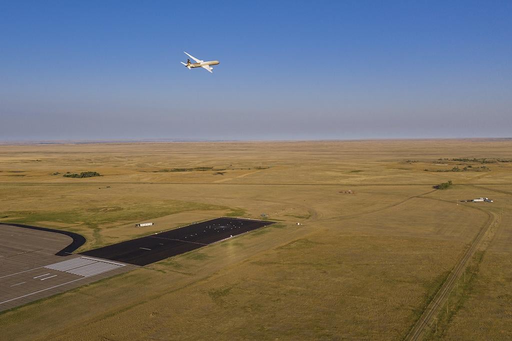
“Even more interesting: As we bank the airplane, one engine is partially shielded by the fuselage from any observer located laterally. And that was an idea that we wanted to really quantify in flight with an airplane because that is something that cannot be measured in the lab.”
For Boeing, the research was aimed at verifying that potential future aircraft configurations could take advantage of noise-shielding effects. “What would it mean if the engines are located in different locations on an airplane?” Czech asks. “The flight-test results don’t directly translate into some quieter noise procedures,” he notes. “This provides really fundamental learning.”
Lessons learned from the tests will therefore be important to developing potential future ultra-low-noise configurations, such as hybrid wing-body aircraft designs with engines mounted above the fuselage. “This was the first time that we had the opportunity to investigate shielding and reflection at full scale and full fidelity with all of the real geometry and flight effects,” NASA’s Thomas says. “This is a really unique part of this experiment.”
Although data is still being analyzed, he adds, observers anecdotally recorded a notable noise-shielding effect during the tests.
The test matrix covered more than 50 unique configurations and was designed to identify, quantify and characterize the major airframe sources of gear, flap, slat and trailing edge noise. “It also gave us information on the interaction effects between components such as the gear and flaps and the effect of flap-on-gear noise. We saw, for example, how landing gear noise reflects off of the airframe with a deflected high-lift system,” Thomas says.
“Through it all—pandemic, weather and everything else—we exceeded our metrics and had a successful test,” he adds. The test design, the flight-test instrumentation and the evaluation of ANOPP with data from the Glasgow program are expected to collectively improve NASA’s ability to more realistically predict the noise characteristics of the TTBW ahead of its planned development starting around 2022.
Editor's note: This article was updated to correct the credits for the graphics.

Related Content