Much is made of the ability of crossover narrowbody jets to bring right-sizing to many airlines’ routes. The trip costs are clearly advantageous when a route does not have the capacity to fill enough seats in larger narrowbody types, particularly if the airline wants to offer a schedule that attracts business travelers as well as leisure passengers.
That advantage is useful, but even more worthwhile is if seat-mile costs begin to approach those of the large narrowbodies. Improved engines, of course, make a difference, but other contributions are also needed, such as in the field of wing technology.
With the Airbus A220 being a clean sheet design when first announced as the Bombardier C Series and Embraer’s E-Jets E2 family being almost an all-new (the double-bubble fuselage remained), the OEMs had considerable space in which to work to effect major wing improvements.
Jean-François Parent, vice-president, head of A220 engineering and chief engineer at Airbus, describes some of the original requirements for the wing. “First, the A220 was the first aircraft in the industry designed to successfully integrate a new generation engine with high bypass ratio. This required many design iterations to find the perfect balance between engine location, wing geometry and main landing gear design,” he notes.
“In terms of aerodynamics, the high level requirements were maintaining the wing shape particularly for the 1g cruise condition, as well as tight symmetry tolerances. The wing torque box material is composite made from a proprietary RTI (Resin Transfer Infusion) process developed by Bombardier in Belfast (now Spirit) at the time, which uses dry fabric infused with epoxy and then autoclaved. The stiffness of the wing torque box was tailored to deliver the optimal aerodynamic shape under the 1g cruise condition,” Parent adds.
“For slats, the requirements were mainly to maintain a trailing edge step relative to the Wing Under Slat Surface (WUSS) that is sufficiently tight. The lower slat trailing edge design was also tailored to suit a deflected wing in flight so that it would follow the wing shape,” he reports.
With a requirement to operate at airports with challenging takeoffs and approaches such as London City (LCY), a great deal of work was done to obtain the highest lift possible. One key decision involved sealing off – as much as possible – the slat track penetrations into the fixed leading edge cut out.
“For flaps, made primarily from composites, the main requirements were to deliver as smooth a surface as possible and once again maintain a tight step tolerance between the top of the flap and the wing fixed trailing edge,” Parent explains. “The flap profile tolerance is also tight to be in line with the wing profile tolerance. Rigging capacity and stiffness for skew detection was also considered in the overall flap design mechanically. Flap stiffness was refined to maintain deflection requirements relative to the wing torque box at cruise, while the design of the flaps and their sealing requirements also contributed to cruise performance. Ground and multi-function spoilers were designed and optimized with pre-bow conditions which ensured no lift-off below 1g cruise with wing bending at their interface with the flaps.”
“Besides the winglet – which is also fully composite with the exception of the leading edge and the Lightning Fault Current Return Network (LFCRN) – no other wing tip devices were elected.”
According to Parent, one of the main drivers was to reduce the amount of unusable fuel left in the tank, so low points were studied and the collector tank was carefully designed. “As the wing is a fuel tank, its design necessitated the incorporation of specific design features that provide multiple layers of protection against ignition sources, including direct and indirect effects of lightning strike,” he confirms.
The design of the root joint was mainly determined by production cycle time requirements, which drove features like the integral rear spar splices on the center wing box and forward and aft spar, to minimize loose fitting and fiddling. Parent says that it also allowed for the top stringer tension fittings to be pre-installed at the facility in Belfast. Dimensional analysis and management of part geometry and gaps enabled shimming to be minimized within allowable limits.
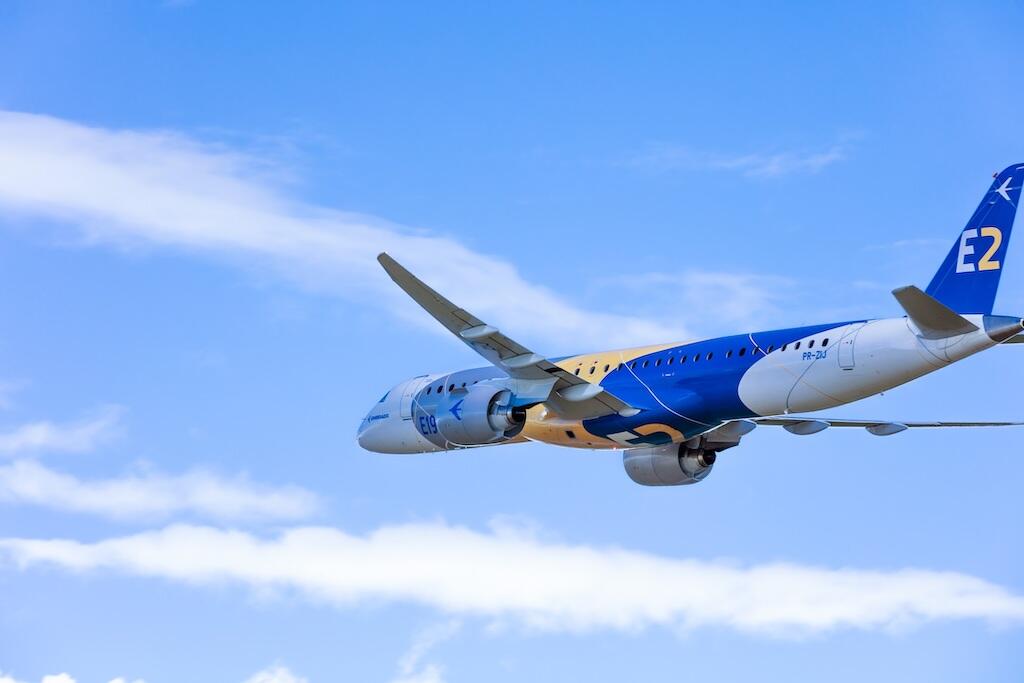
Daniel Galhardo, director of strategy at Embraer commercial aviation, states that from the beginning, the focus of the E2 project was to produce the most efficient airplane in its category, ever. “The wing makes an enormous contribution to that. To reach such ambitious targets the wing had to be extremely efficient – so Embraer decided that each aircraft in the family would have its own bespoke wing, optimized for that aircraft, rather than sharing the same wing across the family as with other aircraft families. This was a significant investment for the program,” he recalls.
“Our engineers also designed the wings with the highest aspect ratio ever used on a commercial jet. High aspect ratio significantly reduces drag and is therefore more efficient and less noisy, however the impact on weight is considerable. To keep the structure light, our new generation fly-by-wire (FBW) system was instrumental in being able to reduce load on the wings in critical phases. Additionally Embraer applied state-of-the-art technology to design a more efficient flaps and slats system, using simpler and lighter mechanisms compared to other commercial jets,” Galhardo remarks. “On top of all that, multidisciplinary optimization was used extensively to improve all pieces of the wing. As an example, these exercises revealed that winglets were not the best solution for this wing – a planar wingtip was better suited to increase the aspect ratio even further and keep drag low.
Initial designs, of course, almost never make it through to the final product. As development progresses, refinements – often seemingly minute – are continuously made to ensure the final wings are fully optimized.
The integration between the wing and the engine was a challenge, as the PW1900G has a fan diameter of 73 in and a fan case diameter of 79.0 in, whereas the CF34-10E on the E1s has a fan diameter of 53 in and case diameter of 57 in.
“The big diameter of the engine and its heavier weight represented a huge challenge to optimize aerodynamics, structural integration and aeroelastic issues in a flexible wing. Innovative solutions were developed for the structural connections that brought 400 kg of weight reduction,” Galhardo confirms. “But the most relevant refinement of the E2 family was the wing optimization of each member of the family leading to three dedicated wings, meaning we made none of the compromises on efficiency found with a common wing.
Recalling the most important refinements on the A220’s wings, Parent begins with the reminder that two designs were being developed, one for the -100 and the one for the -300. “During the development, it was decided certain components would be common between the two. The wing torque box outer mold lines are identical in design and features, however the skin and spar thickness would be increased on the -300 given the higher loads. This drove some minor geometry differences,” he comments. “Minimizing weight was also a key factor. Thus, further refinements were done on the wing skins, spars correction giving some spring back on the skins and the spar.”
The intended outcome for all this work by both OEM’s teams was to create wings which deliver a key advantage over those of the competition. Unsurprisingly, each believes they have the upper hand.
“The RTI wings were designed to be aerodynamically efficient,” Parent emphasises, as he makes his case for the A220 wing. “The RTI process utilizes dry fiber composites and delivers manufacturing advantages over conventional pre-preg including higher deposition rates and the elimination of restrictive material shelf-life limitations. By deploying integrally stiffened composite skins with co-cured stringers as one piece, the number of fasteners is kept to a minimum. The patented RTI process delivers parts with zero porosity and superior geometry control. Also, there are no skin panel joints as seen on previous traditional metallic wings.
“The composite wings were also lighter by comparison to metallic wings. At the time of development, there were not many aircraft in this category with composite wings. Stiffness was also something that was well tailored with a composite wing, taking advantage of composite properties. Overall maintenance was also considered (direct maintenance costs). For example, the winglet joint is a tension joint – this was driven by customer support requirement to be able to swap out a whole winglet in one shift,” the VP states.
Acknowledging that aircraft in the sector other than the E2 family use similar Pratt & Whitney engines, Galhardo highlights that the wings – as well as other aero and system innovations – are an essential differentiator for the E2. “The wings are a major part of the reason the E2 posts better efficiency, emissions, and noise data, than any other aircraft in the segment,” he declares. “The highest aspect ratio ever made for the wing of a commercial jet translates directly into fuel efficiency, lower emissions, and quieter operations.”
Galhardo also points to the attention to detail such as the planar wingtip devices which, again, were optimized for each member of the E2 family. In fact, many were surprised when use of these was announced as opposed to winglets.
“The wingtip device is designed to reduce induced drag on the tip, and choosing the optimal device is a complex process closely related to the way the entire wing works. The perfect match is a result of a study of multiple options, and the innovation is on the methodology behind it. That allowed us to study a huge range of options and truly select the best one,” Galhardo states confidently.
Engine technology will, of course, continue to be the major factor regarding fuel efficiency and emissions, but every efficiency, every percentage improvement in other areas needs to be sought and exploited.

Related Content

Comments