Certified maintenance facilities that specialize in radomes will use a moisture meter to detect water in sandwich honeycomb structures.
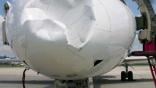
Rain droplets striking an aircraft nose at 500+ knots are extremely abrasive, causing erosion of edge sealants. Once the outer coatings, which includes the paint and anti-static coatings, are compromised by pit marks and paint damage, water will eventually seep into the interior of the radome.
Even small amounts of water, which may “wick” into the fibrous materials, will freeze at altitude, causing delamination of layers. This can create a progressive failure of the radome materials. Any hole, regardless of size, can cause major damage to a radome since moisture can enter the radome wall and cause internal delamination.
Not only does the trapped water compromise the structural integrity of a radome but it also affects the radar’s performance. Trapped water can produce a shadow on the radar image. If enough moisture collects, the radiation pattern will be distorted and the transmitted signals and return echoes seriously blocked (or “attenuated”). Repeated freeze/thaw cycles will cause delamination and core disintegration to be surrounding honeycomb cells. The result of this can be the aircraft getting a false reading on storm cells on the radar scope or, inversely, the radar being misdirected and pilots missing a storm in front of them.
Certified maintenance facilities that specialize in radomes will use a moisture meter to detect water in sandwich honeycomb structures. A moisture meter detects moisture pockets in aircraft radomes by measuring the radio frequency dielectric power loss of material in contact with the electrode sensor.
Damage Caused By Static Discharges
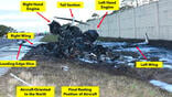
On Jan. 3, 1992, a Beech 1900C on approach into Saranac Lake in New York intercepted the glide slope from below and then deviated above the glide slope. About two miles outside of the marker, the aircraft was at a full fly-down deflection when it entered a descent varying from 1,200 to 2,000 fpm. The aircraft struck a wooded mountain top 3.9 nm from the runway, fatally injuring two people and seriously injuring two others. Evidence was found of inadequate electrical grounding between the radome and fuselage which, when combined with the existing weather conditions, may have produced precipitation static interference causing the glide slope indications to be unreliable.
WeatherGuard, an aerospace manufacturer that specializes in lightning protection of aircraft components, highlights the importance of properly designed and maintained radome components. “When a plane flies through a storm, it is subjected to significant electrical current even if not in an actual lightning strike,” the company says. “As the air ionizes, lightning leaders can begin sending high voltage current through a radome, even if it is not in the form of a direct strike. Static electricity and near strikes can still damage a radome.”
According to FAA Advisory Circular 43-14, “Maintenance of Weather Radar Radomes,” the most frequent damage to radomes are holes in the structure caused by static discharges. As an aircraft flies through an electrically charged atmosphere, electrical charges accumulate on an aircraft’s surface, resulting in high voltage streamers being discharged from the aircraft’s pointy surfaces, to include the radome.
A properly designed and maintained radome must have the ability to shed this static electricity. Designers utilize a combination of anti-static coatings and lightning diverter strips. The diverter strips continuously collect static build-up and conduct it to the airframe without sparking or arcing.
Transmission Properties
The radome needs to have desirable transmission properties to enable the airborne weather radar to function adequately. According to AC 43-14, a properly designed and maintained radome permits the passage of the radar’s transmitted signals and return echoes with minimum distortion and absorption. This requires that aircraft radomes be precisely constructed. The slightest change in their physical characteristic, such as excessive layers of paint can adversely affect radar system performance.
To allow passage of transmitted signals, the radome should have a certain “electrical thickness.” The electrical thickness is related to its physical thickness, operating frequency of the radar, and the types of material and construction used. A very small variation in physical thickness may cause a sizable variation in electrical thickness. A variation of more than 0.005 inches from the designed thickness will impact the transmissivity of the radar signal. Radar efficiency, definition and accuracy of the display depend upon a clear, undistorted, reflection-free antenna view through the radome.
The performance of a radome is characterized by multiple parameters, which we will discuss in Part 3 of this article.
Know Your Radome, An Important Structure, Part 1: https://aviationweek.com/business-aviation/safety-ops-regulation/know-y…

Related Content