In “Enterprise,” one of the most underrated of the "Star Trek" television spinoffs, future Capt. Jonathan Archer repeatedly crashes his model airplane because a turn of the winds found his craft without the necessary lift. His father reassures him, saying, “You can’t be afraid of the wind, learn to trust it.”
As a pilot, this scene troubled me for some reason. Did I fear the wind? Except for a towering thunderstorm parked on the end of a runway threatening a microburst, I did not think so. But I certainly did not trust it. I’ve had too many landings in windy conditions where something (not me!) happened at the last minute to rob my wings of the lift they needed. When my flight manuals gave me the opportunity to adjust my approach speed, I did so, and those surprises seemed to happen less often. In most of those manuals, that additive was recommended but not required.
Until you were burned a few times, you might have been tempted to forgo the additive. “I never needed it before.” This begs the question: How large is your margin to an angle of attack (AOA) limit on short final? If that convinces you to include the speed additive on your next flight on a gusty-wind day—and I hope that it does—there are still two more questions to answer. First, on what wind will you base the additive; i.e. all or part of the headwind or crosswind, and what about a gust? Second, once you’ve added the necessary margin, do you hold that to the runway threshold or get rid of it? And if you elect the latter, when and how?
How Large Is Your Stall Margin at Approach Speed?
When flying a transport category aircraft, your approach speed cannot be lower than reference speed, Vref, which may not be lower than 1.23 times the reference stall speed in the landing configuration, Vsr. Moreover, 14 CFR 25.143 further specifies that when landing, the aircraft must be maneuverable and free of stall warning or other characteristics that might interfere with normal maneuvering up to 40 deg. of bank with symmetric thrust while flying a -3-deg. flight-path angle. While we all think of stalls as occurring at certain airspeeds, we know that stalls actually happen at particular angles of attack, what an aeronautical engineer calls the “alpha.”
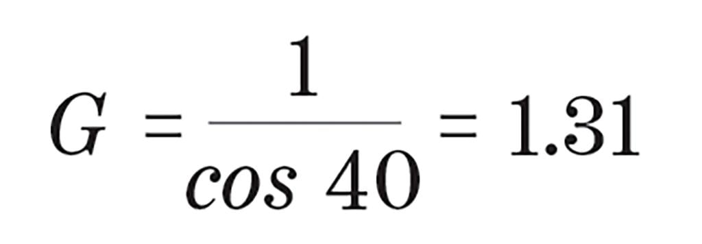
But how do we translate that 40-deg. bank angle to Gs? We are taught early that a level 60-deg. bank turn requires 2g. The math behind that is:
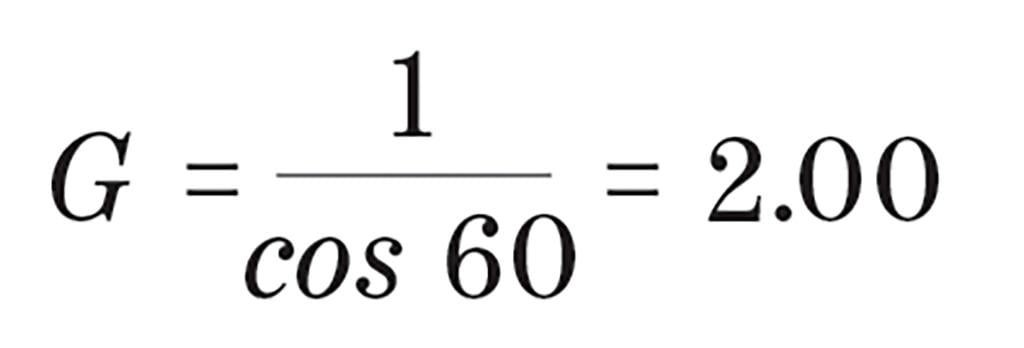
A 40-deg. bank turn requires:
So, all of that provides us with two concepts when trying to understand how close to a stall we can come, but how can we turn that into practical knowledge in the cockpit? For most of us, our only G-meter is the “seat of our pants.” But we do have attitude indicators and keeping to less than 40 deg. of bank in coordinated flight should keep us safe, provided we maintain a healthy margin above the stall angle of attack. If you have an AOA indicator, you have an advantage. But just what is angle of attack?
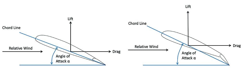
Most of us learn early on that the AOA is the angular difference between the chord line of the wing and the relative wind of the aircraft cutting through the air. That isn’t precisely correct, but it is close enough. We can change the effective chord line of the wing with leading- and trailing-edge devices, such as slats and flaps. The shape of the aircraft itself may create lift and the angle upon which the wing is mounted versus the reference provided to you on your attitude indicator, the “angle of incidence,” will also alter the wing’s AOA to your perceived AOA. But for we pilots, thinking of AOA as a function of the relative wind and the wing is good enough.
Left unsaid is that an angle is something you measure in units, usually degrees. It is a number, such as 15 deg. We also learn that the wing stalls at a particular AOA. Here again that is given in degrees, such as “the wing stalls at 18-deg. angle of attack.” As pilots, we do not use AOA measured in degrees because that measurement varies too much with flight condition and aircraft configuration.
Airplanes that do display “AOA” are usually showing us “normalized” AOA. That is just a fancy way of saying they are giving you a ratio of the actual AOA (in degrees) divided by the stall reference AOA (in degrees) to give you a number between 0.00 and around 1.00. Yes, the number can actually exceed 1.00 as the wing still produces usable lift, but for us pilots, thinking of 1.00 as our upper limit helps our understanding of the concepts. The maximum allowable isn’t necessarily the maximum achievable. A fly-by-wire airplane may use a lower AOA to prevent overshoots. An airplane with a conventional stick pusher may do the same to ensure the system activates early enough. In either case, your avionics do the math for you, but a common formula for normalized AOA (NAOA) is:
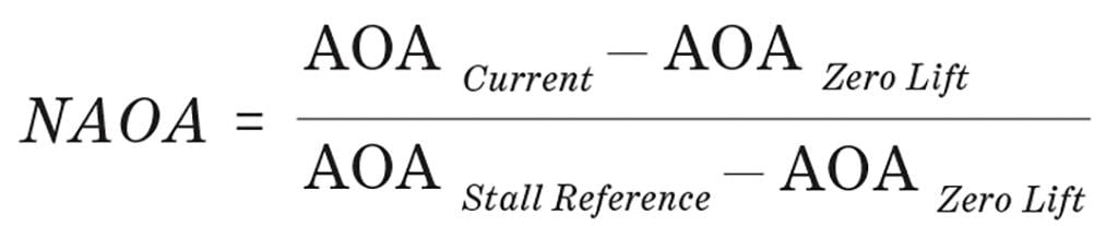
Where each AOA term is measured in units of degrees, the resulting NAOA is a ratio and has no units. We typically think of 1.00 NAOA as the stall AOA, but the real value is usually a bit higher. An example of that could be 1.06 for the stall reference AOA and 1.10 where the wing actually stalls. While far from universal, most aircraft in my logbook flew final approach at an NAOA around 0.60 and would give you a stall warning (limiter, stick shaker or pusher) between NAOA = 0.85 and 0.97.
We can make all of this truly useful if we look at what an engineer would call a “notional,” or hypothetical, aircraft. The charts and graphs that follow may not precisely reflect your airplane and ignore things like ground and Mach effect, but they serve to illustrate the concepts that you can apply to your aircraft to better understand the principles. Stall reference speed, Vsr, is determined at 1.0g and the stall speed varies with the square root of G loading. Plotting NAOA versus G for these two conditions proves very useful.
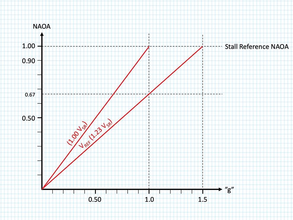
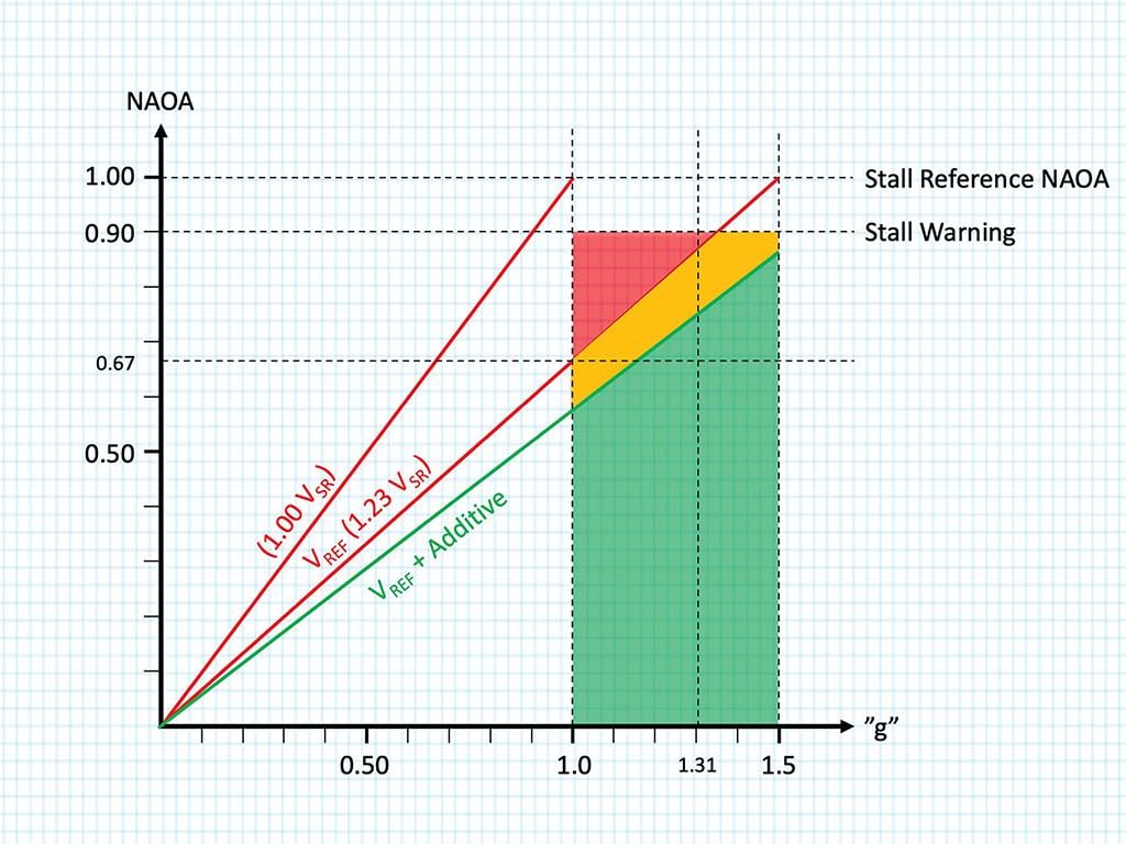
Notice that the intersection of our Vref line and 1.0g comes to 0.67 NAOA. This would make a good target NAOA on approach for our notional aircraft. If the notional aircraft has an alpha limiter or stick pusher that activates at 0.90 NAOA, we can draw an envelope to indicate an area of operation where the airplane is maneuverable without stalling. Of course, we do not want to operate below Vref, but this area is available to us in the event of wind shear or another non-normal condition. This becomes useful to us, realizing that if we see an NAOA greater than 0.67 on final approach—because of turbulence, for example—we are “eating into” our stall margin.
Many manufacturers add 5 kt. to Vref, or even more if wind conditions dictate. This results in a lower line on the NAOA G-graph and expands our stall and maneuver margins. Imagine yourself flying at 1g at Vref. You are given a margin before stall warning (the red zone above the line) as well as a maneuver margin. That margin was determined by allowing for a 40-deg. turn on a 3-deg. glidepath, which comes to 1.31g. These margins can be “eaten” by a sudden gust of wind or turbulence. We certainly don’t want to find ourselves flying this slowly low to the ground when a sudden loss of airspeed activates a stick pusher! Fly-by-wire aircraft could find themselves nearing an “alpha limit,” limiting pitch authority. In either case, it would be wise to avoid high angles of attack.
The Impact of Sudden Gusts on NAOA, G Loading and Stall Margins
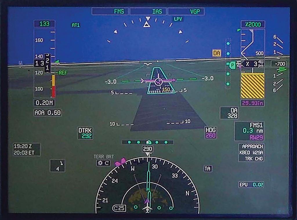
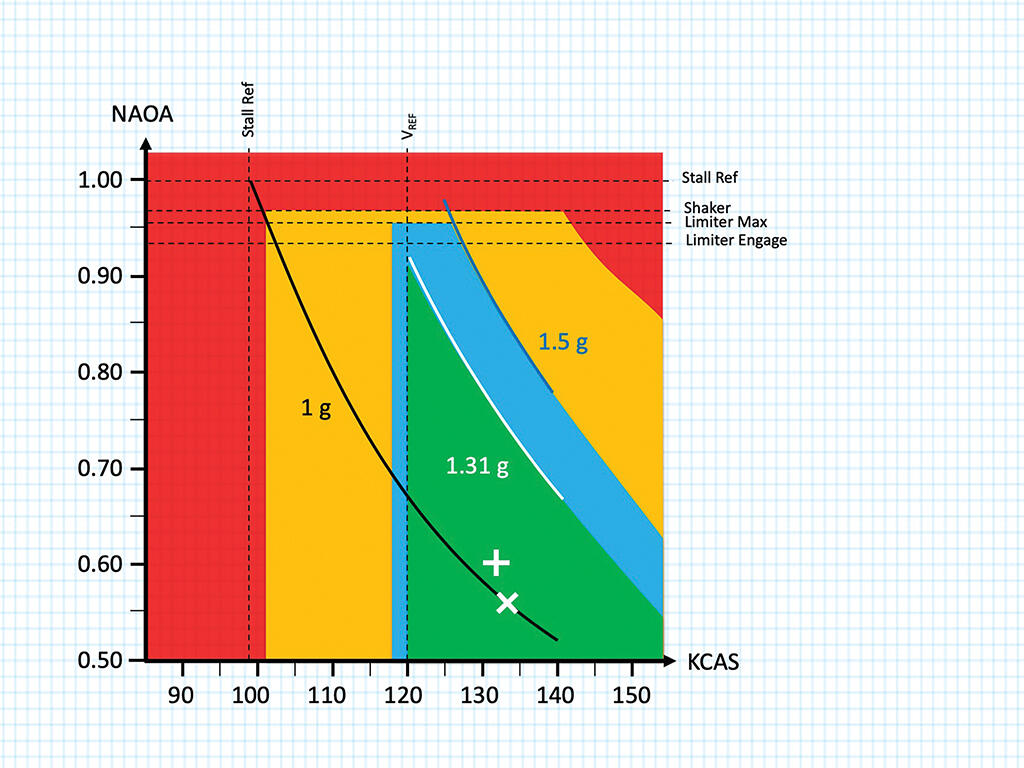
Most pilots are primarily focused on airspeed even if presented with an indication of NAOA. The NAOA-KCAS chart shown for our aircraft is from a recent flight where Vref was 120 kt. (at an AOA of 0.67) and the winds were at 10 kt., gusting to 18, making our target approach speed 120 plus half of 10, plus 8, for a result of 120 + 5 + 8 = 133 kt. (at an AOA of 0.57).
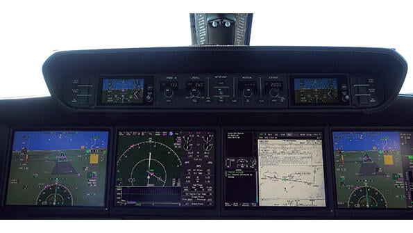
Of course, nothing is ever static on a gusty day and just as we expect the airspeed to bounce around, so too does the NAOA. We can see from the photo of the pilot’s synthetic vision that a gust has increased the NAOA to 0.60 and that on the chart our target approach airspeed (shown by the “X”) moves up and to the left (shown by the cross). Our green zone is defined by Vref on the left and the G-loading that equates to a 40-deg. bank turn in level flight (1.31g) to the right. The manufacturer of our notional aircraft has provided us a margin, shown in blue, before we enter a zone of “low speed awareness,” which provides an additional margin before stall warning, even at 40 deg. of bank, shown in red. Passing the threshold and entering the flare, it will be OK to go below Vref (in calm conditions) since we no longer need all of the maneuver margin for the design parameter of 40 deg. of bank.
So, it should be apparent that getting below Vref is not a good idea and that when it gets windy, you need to add to your approach speed to avoid doing that. But by how much?
Half of What Wind and How Much of What Gust?
Some aircraft manuals say you should add half the steady wind and the full gust increment to your approach speed. But that is far from universal. Looking at several aircraft from the smallest Challengers and Falcons to the largest Airbus and Boeing jets reveals the breadth of the variation. You might add a half, a third or none of the steady wind, or the headwind. Most will have you add all of the gust. Most will limit you to a 20 kt. total additive, but some lower this to 15 and even 10 kt.
 The reasons for variation may seem arbitrary but might be more strongly correlated to aircraft design and recommended landing technique than one might suspect. All aircraft should be concerned with at least the headwind component because of the nature of winds low to the ground. The wind normally decreases as you near the runway, particularly below 50 ft. Adding at least 5 kt. or half the headwind is a way to mitigate that decrease. An airplane that lands in a crab may only be interested in the headwind, since sideslip is not a factor. An airplane that lands in a sideslip (the so-called “wing low” method) or a de-crab will have to consider all of the wind, regardless of direction.
The reason for including a wind additive to your approach speed is clearly designed to prevent landing with too little stall margin should the winds change. But landing with too much speed presents its own set of problems.
If you land with that extra speed, will you still be able to stop on the runway available? Many manufacturers recommend you lose any additive prior to crossing the runway threshold. (More on that later.) But that will require considerable judgment.
Will this extra speed throw you into a higher approach category? Some aircraft circle at their final approach speed and an extra 20 kt. could very well result in the next higher approach category. This could require a higher circling altitude as well as higher weather minimums.
Will the extra airspeed create problems with tire groundspeed limits? Even if your aircraft manufacturer has not posted such limits, the tire manufacturer most certainly has. These limits can be a factor at higher pressure altitude airports, especially on a day with a low headwind component. On a gusty-wind day an additive might bring tire groundspeed limits into play even at lower pressure altitudes.
Will the lower deck angle make it possible to contact the runway nosewheel first? If your airplane flies its final approach in a relatively nose-low attitude, touching down too fast could result in a nosewheel-first landing with the risk of a nosewheel landing gear collapse. Thus the limits to the approach speed additive should take this deck angle limit into account.
For these reasons, and maybe others, some manufacturers recommend you get rid of the airspeed additive prior to crossing the runway threshold.
Lose or Keep the Additive?
Here again manufacturers differ. Many Boeing, Airbus and Dassault aircraft leave the additive in until the autothrottles retard for the landing. As noted, some manufacturers recommend the pilot remove the additive prior to crossing the threshold. There are many reasons for caution, but if you decide to lose the additive prior to the runway threshold, how do you do that?
I’ve tried two methods as the pilot flying and I’ve witnessed both methods as the pilot monitoring. Both methods work. Sometimes. But not always. For that reason, I consider both methods to be bad ideas.
Bad Idea One: With or without autothrottles, some pilots will try to get a feel for the gust and try to time pulling the throttles so as to arrive over the threshold at Vref. I found this easier to do in the Gulfstream G-V with approach speeds near 110 kt., but even then, I got it wrong occasionally. With aircraft requiring higher approach speeds, things are happening too fast for me to time the gust consistently.
Bad Idea Two: With autothrottles, some pilots will insert the targeted speed manually with the additive and select “auto” mode at a moment when they believe the speed is increasing. Here again, the judgment required at higher approach speeds makes this a hit-or-miss proposition.
I consider these bad ideas because a wind gust cannot be predicted consistently. My solution for the last 10 years has been to keep the additive until the autothrottles retard for the landing flare, and to ensure I have enough runway in case I touch down with all of the additive speed.
Landing Distance Impact
When I suggest holding the speed additive to the runway threshold to other pilots, the first reaction is often to ask about landing distance. The landing performance charts in my current aircraft include a section of up to 20 kt. additional speed crossing the threshold. I’ve seen other manufacturers with 10-, 15- or 20-kt. allowances.
The next objection will be, “What if the gust hits me at just the wrong time and I end up 20 kt. fast?” Let’s look at another hypothetical.
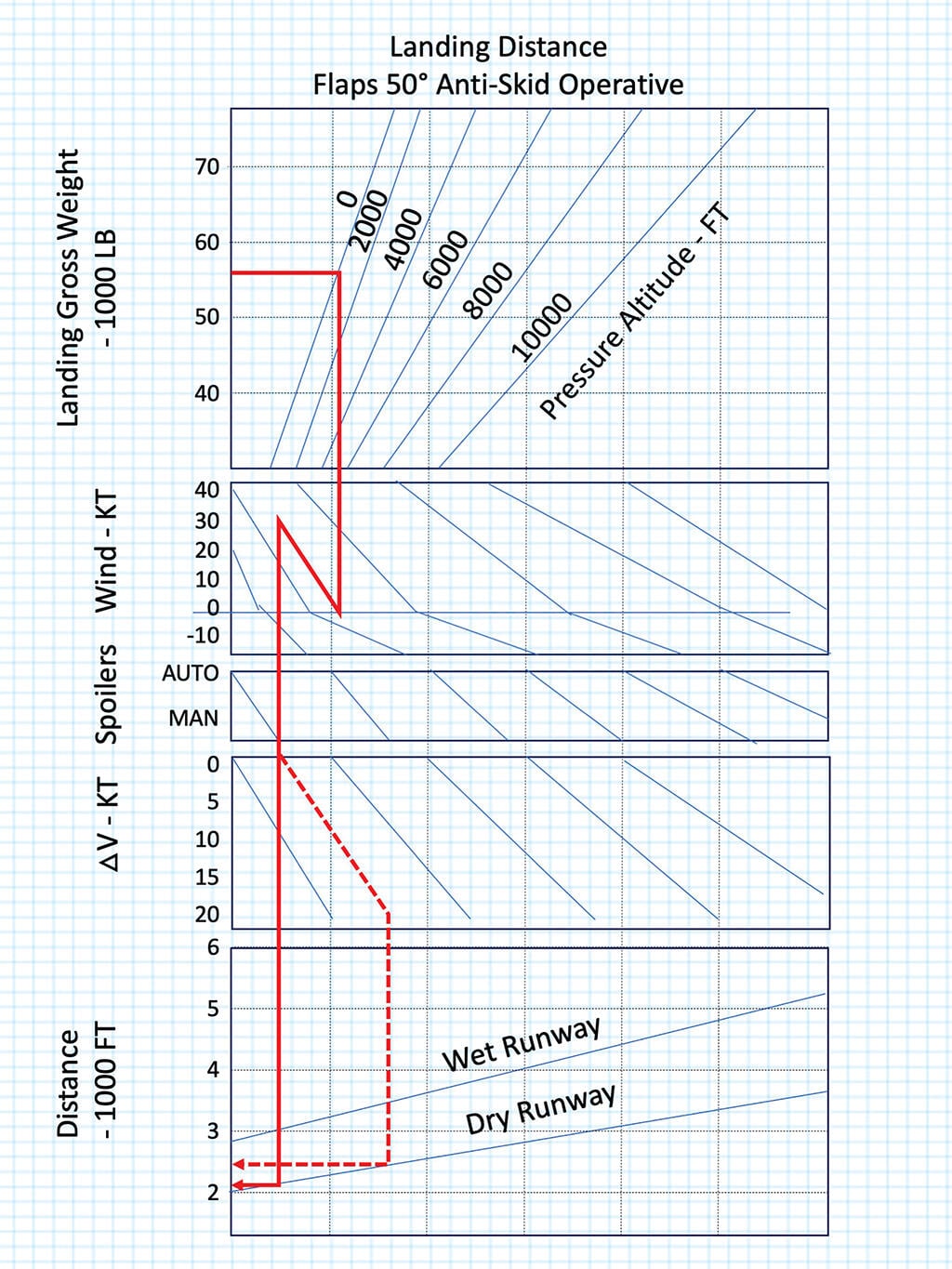
Let’s say you have a Vref of 120 kt. and a wind straight down the runway at 20 kt., gusting to 30 kt. Your charts, like mine, have a section for a headwind up to 40 kt. and a speed additive up to 20 kt. You compute your landing distance for a headwind of 20 kt. and a gust of 10 kt. Your manufacturer recommends half the steady and all of the gust as an additive, regardless of direction, so your approach speed is 120 + 10 + 10 = 140 kt. That 10-kt. gust treats you unkindly and you end up at the threshold at 150 kt. airspeed. If your performance data included all of that additional wind you won’t have a problem; your groundspeed will still only be 120 kt.
If your flight management system automatically computes landing distances, you will need to ensure you have the right data in, to get the right data out. It may seem to be common sense to reduce the headwind entry as being conservative; however, it paints an inaccurate picture of your actual performance and places a subtle pressure on you to remove the additive.
My usual method is to precompute the maximum additive for my normal landing weights at a sea-level airport. I use Teterboro Airport (KTEB), New Jersey, because (a) we go there often, and (b) it is usually gusty. In my current aircraft I find that even landing 20 kt. fast never increases my landing distance by more than a third on a dry runway and that is good enough for the shortest runway there. If the actual conditions are worse than that, I know I need to dig into the Airplane Flight Manual charts. If I cannot make the numbers work with the additive, my plan is to find someplace else to land. Over the years, I have had to do that twice.
In my current aircraft, a Gulfstream G-VII-G500, the chore is handled automatically by the avionics, giving me a graphic representation of the resulting landing distance. If I elect to keep my speed additive to the runway threshold, I will know how that will impact my stopping distance.
Keep the Airplane Flying Until It’s on the Ground
Unlike the young Jonathan Archer in “Star Trek: Enterprise,” we don’t need to be afraid of the wind nor do we have to trust it will behave as we expect. We can simply allow for it to misbehave and plan our approach speed accordingly. On a gusty day, flying an approach speed without a wind additive risks running out of flying speed prior to the landing flare. Your only options may be to add to your approach speed or to divert. An additive may be required, recommended, forbidden or not mentioned at all.
controller.
I recommend you research your manuals, see what flexibility you have, and fly the additives if you can. If the resulting landing distance or threat of running out of speed is too great, find another place to land.

Related Content