This article is published in Aviation Week & Space Technology and is free to read until Aug 17, 2024. If you want to read more articles from this publication, please click the link to subscribe.

Thrust Reversers Go More Electric, Lighter Weight

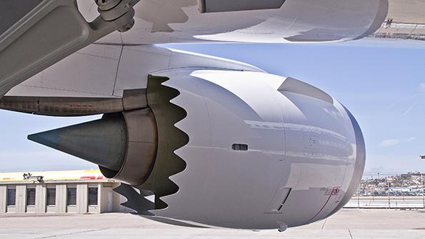
Boeing 787 thrust reverser

Like most modern commercial jets, the Boeing 787 uses a cascade-type thrust reverser.

Credit: Collins Aerospace

As sustainability goals push more systems toward electromechanical actuation solutions, weight savings and maintenance-efficient designs, thrust reversers are unsurprisingly trending in the same direction.

“We expect aircraft entering service during the next cycle to be more electric, with the potential elimination of all hydraulic and pneumatic systems eventually,” says Satish Narayanan, vice president of engineering and technology for advanced structures at Collins Aerospace. “When that happens, we expect that nacelle and thrust reverser assemblies would have to become more electric. We are working to develop suitable architectures and enabling technologies.”

Reinforcing the arresting action of carbon or steel brake stacks upon landing, an aircraft’s thrust reversers are part of the nacelle system and redirect forward or radially the rearward thrust of its turbine engines, slowing the aircraft’s forward motion. Most thrust reversers fall into three categories, explains Andrew Momotiuk, senior engineering manager of actuation technologies within Eaton’s aerospace group: cascade, pivot door and bucket.

Momotiuk says that cascade reversers use linear actuation to translate, or move, a cowl and deploy blocker doors in the bypass airflow to reverse the thrust. When the thrust reverser is deployed, this cowl moves axially along the nacelle, which allows the high-bypass airflow to be expelled radially and forward from the engine instead of axially at the rear of the engine.

The blocker doors are located throughout the annular bypass flow region of the engine. A part of the nacelle, they prevent the high-bypass airflow from flowing out the rear of the engine. Momotiuk points out that there are numerous blocker doors that deploy and close off a majority of the annular area of the high-bypass airflow. Cascade-style reversers are used on most newer single-aisle and widebody commercial aircraft.

The pivot door, or clam shell reverser, Momotiuk notes, uses angular motion to block the bypass airflow at the doors’ specific locations. There may be two or four doors located circumferentially around the engine. “These were previously used on older Airbus A321 and A340 aircraft and some regional aircraft but have been replaced with cascade-style thrust reversers on the modern versions of those aircraft,” he says.

Bucket, or deflector door reversers, are located at the rear of the engine and reverse both the bypass airflow and the core airflow generated by the engine, says Momotiuk. “This uses angular motion to rotate the bucket in order to reverse the airflow and continues to be common on regional jets and business jets,” he explains.

Eaton thrust reverser system
Eaton is applying electronic synchronization to thrust reversers and other aircraft systems to improve performance and maintenance processes. Credit: Eaton

Momotiuk says Eaton manufactures hydraulic actuators, control valves and locks. In addition, the company has developed and manufactures electromechanical actuation (EMA) systems with synchronization technology, having thrust reverser applications, to increase lifespan and overall efficiency.

“We are transitioning to EMA architectures for thrust reverser actuation and using synchronization technology that was first developed for flap systems,” he says. “We are also leveraging high-voltage DC motor and electronics to improve the actuation system performance and envelope. At the same time, we are balancing the use of mechanical and electrical means for motion control of the actuators. This reduces the wear on the mechanical parts to limit or eliminate any need for maintenance.”

Momotiuk adds that advancing the technology from hydraulic to electromechanical eliminates hydraulic actuation system maintenance around the engine. “Also, by using electrical synchronization instead of mechanical coupling flex shafts, installation and integration of the actuators in the nacelle is simplified, eliminating the rigging process steps for mechanically coupling the actuators using flex shafts,” he says. “By enabling the removal of mechanical couplings and hydraulic lines from the engine nacelle, this allows for some weight reduction at an aircraft level.”

Going forward, Momotiuk says, Eaton is applying electronic synchronization and high-voltage DC capabilities to thrust reversers and other aircraft systems. “These technologies result in performance and maintenance advantages for aircraft operators, including reduced fuel consumption and improved operational efficiencies,” he adds.

Material Considerations

The increased focus on CO2, nitrogen oxides and noise reduction will have a larger influence on thrust reverser design than in the past, according to Narayanan at Collins Aerospace. “Sustainability will become a more critical factor and will drive material selections and thrust reverser architectures and material selections,” he says. “It will also drive the need for improved acoustic technologies, such as multi-degree-of-freedom liners.”

Narayanan also points out that as engine fan diameters have trended upward, the amount of reverse thrust needed has trended downward due to the drag associated with increased fan diameters, the frontal area and external surfaces of the propulsion system. This increased drag helps offset the amount of reverse thrust needed upon landing.

“To a certain degree, we can take advantage of this by shortening the length of the thrust reverser and possibly reducing the reverser stroke,” he says. “Both help to reduce the overall fuel burn during forward thrust.”

Narayanan also notes that engine temperatures have trended upward, driving the need for newer, higher-temperature materials in the reverser and exhaust nozzle. Ceramic-matrix composites are among those he reports being considered. “We expect these trends to continue and that thrust reverser architectures will take advantage of larger diameters (where possible) and adapt to more intense thermal environments,” he says.

Nikkiso supplies composite cascades, blocker doors and torque boxes, which are the essential load-bearing components of thrust reverser systems. They are located on the forward side of the cascades and configured to transmit tension loads from the cascades to another component, such as the V-blade ring, which engages the engine. According to Satoko Takigawa, general manager of marketing and sales for Nikkiso’s aerospace division, the company’s cascades are installed on most commercial aircraft engines employing cascade-style thrust reversers.

“A principal manufacturing change was a transition from metal to carbon-fiber-reinforced polymer, which has led to significantly lighter weight,” she explains. “This contributes to less fuel burn and less carbon emissions while maintaining the same level of stiffness and strength as metal.”

Asked about durability and life limits, Takigawa reports that the cascades are designed to meet higher damage tolerance requirements, resulting in a very low percentage of replacement or reworking. “Even if it is damaged during flight, as long as it is within the damage [tolerance] criteria, we can assure it would be durable until the next maintenance cycle of the aircraft,” she says. “Also, with the improved layup configuration, the cascade is less likely to crack.”

Takigawa adds that Nikkiso’s layup configuration incorporates a thinner, lighter design while still meeting the cascade’s load condition requirements. “The cascades remain on wing through the life of the aircraft,” she says.

Takigawa says the company uses a “one-shot curing” process for the composites. This, she explains, is the process of fully curing—polymerizing—a large composite component or structure in a single curing cycle without the need for multiple curing steps from different angles. “By design, fabrication by one-shot curing results in a highly durable product with fewer parts to maintain,” she says.

Nikkiso is currently in the research and development phase of a new material that Takigawa says would enable a shorter cure cycle time, leading to higher production rates and less energy consumption in the production process.

Advanced Manufacturing Techniques

Curtiss-Wright supplies linear variable differential transformers (LVDT) and rotary variable differential transformers (RVTD), along with solenoid operated valves (SOV), for a variety of thrust reverser applications. According to Mike Barnes, director of business development for the manufacturer’s sensors division, the LVDT works with the thrust reverser actuation system (TRAS), while the RVTD has an asymmetric sensing function.

As Barnes explains, the LVDTs and RVDTs are designed to detect the mechanical position of the thrust reverser actuator to determine if it is in the stowed or the deployed position. “It also provides feedback to the flight control computer of its actual position between the extremes of stowed and deployed,” he notes. “The TRAS design differs among aircraft, which is why we supply both linear and rotary sensors. And that depends on how our customer’s TRAS is measuring actuator positioning.”

The SOVs, Barnes points out, form part of TRAS and are used to control larger valves. He reports that they are typically integrated into the isolation control valve (ICV), directional control valve (DCV) and track lock valve (TLV). (Barnes notes that Curtiss-Wright does not manufacture ICV, DCV and LTV components.)

“The ICV system controls whether the TRAS has hydraulic pressure and, therefore, whether it can be actuated,” Barnes explains. “The DCV controls the extend/retract mechanism and is defaulted to the retract position. The TLV is what is known as a tertiary mechanism. It is an additional layer of safety to ensure the TRAS cannot be deployed without command. It incorporates a mechanical locking mechanism—possibly a pin or blade being inserted across the track of the TRAS. These are all used to control the deployment and direction of travel of the TRAS and part of the safety systems.”

In recent years, Barnes says Curtiss-Wright has applied advanced manufacturing techniques to its SOV, LVDT and RVDT products. One such example is laser welding instead of the brazing methods used with older designs.

“Laser welding fabrication also provides the opportunity to eliminate seals in certain areas of the design,” he says. “A laser weld effectively forms a hermetic seal between two separate metallic piece parts, such as a sensor body and connector, or a two-part sensor body. Previously, a separate seal might have been required to maintain hermetic qualities. Laser welding can therefore reduce component count and allow for more optimized mechanical designs—both of which reduce cost.”

Barnes also cites the LVDTs as examples of design change. “LVDTs for older systems were often single-channel devices, which meant that for redundancy, more than one sensor would have to be installed,” he says. “Our LVDTs on newer platforms such as the Airbus A220 and A320neo are dual-channel units, providing built-in redundancy and therefore the potential to install fewer sensors.”

Barnes also notes that Curtiss-Wright continues to grow its sensor portfolio with a new generation of solid-state position sensors, which are now in development. “They offer the potential of being smaller and lighter than their wire-wound inductive equivalents,” he says. “It is possible that such sensors could be utilized in future TRAS designs, but that will be determined by our customers.”