Airfoil design has undergone immense changes as manufacturers seek to produce aircraft that can cruise more efficiently at high transonic speeds. In spite of these advances, high-performance airfoils exhibit stall behaviors completely different from low-performance airfoils used on earlier generations of training and transport aircraft. Specifically, this includes lack of aerodynamic warning and an abrupt loss of lift. Furthermore, these negative effects are exacerbated when the leading edge is contaminated by irregularities such as icing.
One of the direct results of these diverse stall behaviors is that high-performance airplanes have unique characteristics nearing the margins of their respective maneuvering envelopes that are likely to deter from the timely recognition and recovery of an airplane upset.
Some instructional materials provide adequate explanations of the stall behavior of older airfoils in terms suitable for general aviation pilots. Unfortunately, this information continues to be widely disseminated without any regard for the advances in engineering knowledge and is not accurate when describing the behavior of advanced generations of airfoils.
The misconceptions of this outdated information can have potentially dangerous consequences. According to the FAA’s Advisory Circular 120-111 “Upset Prevention and Recovery Training,” “Evidence indicates that training programs using operating procedures from one airplane type may have a detrimental effect if carried over to a different airplane type. This can lead to an upset.” The extensive collection of industry authorities who contributed to the Advisory Circular noted, “The safety implications and consequences of applying poor instructional technique, or providing misleading information, are more significant in upset prevention and recovery compared with some other areas of pilot training.”
The stall characteristics of a wing are affected by a multitude of factors, some of which are affected by deliberate design choices while others occur due to environmental factors. Examples of the former include an airfoil’s shape, the wing’s planform and wing twist. Modern wings are often built with aerodynamic twist, meaning that the cross section of the wing at various locations along its span is composed of different airfoils. This is done to enhance the aerodynamic efficiency of a wing, but it can also cause a distinct variation of stall development at different span sections of a wing. Swept-wing planforms have the tendency to pitch up as the angle of attack (AOA) reaches critical levels due to their characteristic of having stall development begin near the wingtips. Furthermore, separated boundary layers near the wingtips on swept wings do not produce airframe buffeting that is associated with early stall warning on rectangular wing planforms.
Environmental factors such as heavy rain, Mach waves, crosswinds, anti-icing fluids, decayed aerodynamic seals and icing induce significant changes on an airfoil’s and/or wing’s stall behavior. Without exception, these changes universally disrupt the boundary layer’s behavior and lead to unexpected abrupt stalls that occur at much lower angles of attack, and often lead to unrecoverable conditions due to the excessive loss of lift.
Extension of leading-edge or trailing-edge devices as well as flight controls and spoilers will change the stall development. An airfoil’s stall behavior in turbulent flow and at abrupt pitch rates (i.e., the “dynamic stall”) is significantly different from the “standard” explanation of stalls. Exceptionally thin airfoils have a stall behavior that is unlike the two types of stalls that will be discussed in this article. These are just a sample of many factors that have immense influence on the stall behavior of a wing.
The remainder of this article will concentrate on static stalls, or, in other words, a stall produced by a gradual increase in the AOA. Furthermore, we will focus on the stall behavior at airspeeds common for terminal area flight operations (for the more scientifically articulate reader, at lower Reynolds numbers) without the extension of high lift devices or the utilization of boundary-layer control apparatuses. We will compare the effects on maneuvering envelope margins for aircraft that exhibit traditional trailing-edge stalls to the leading-edge stall that predominates on high-performance aircraft. This article will be a translation into “pilot lingo” of the insightful and detailed work done by flight-test engineering teams to provide a much greater understanding of the stall behavior of high-performance airfoils.
Trailing-Edge Stall
During your earliest ground school training you were introduced to the concept of the trailing edge-stall. The trailing-edge stall is prevalent among airfoils designed with the traditional “Clark Y” shape, possessing the typical bulbous shape over the top and a flat bottom. These airfoils are useful at creating lift at relatively slow speeds due in part to plenty of camber. They typically have thickness ratios greater than 16%.
Aeronautical engineers often utilize fine smoke filaments inserted into the airflow of low-speed wind tunnels for flow visualization. This helps them to visually observe the separation and transition on airfoils and flow structures of airfoils. A commonly viewed online video shows the testing of a NACA 4421 airfoil. What do these numbers mean? This designation is from the early days of the National Advisory Committee of Aeronautics. This airfoil has a maximum thickness of 21%. Its maximum camber of 4% occurs at the 40% chord point.
The layer of air along the airfoil’s surface that experiences the effects of friction is called the boundary layer. The air molecules immediately adjacent to the wing’s surface are brought to a near halt by this friction. As the airflow slows along the top of the airfoil, an adverse pressure gradient grows in strength. Before 9 deg., the lift coefficient increases almost linearly, meaning that as the AOA is increased, the lift coefficient increases smoothly.
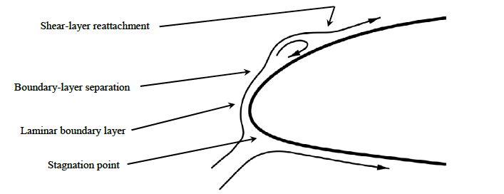
At moderate angles of attack, the adverse pressure gradient causes the boundary layer to “separate,” starting at the airfoil’s trailing edge. The chaotic airflow within a separated boundary layer creates a large increase in drag and is inefficient at creating lift.
As the AOA is increased in increments, the region of separated flow causes the boundary layer to thicken, and it also moves forward along the airfoil toward the leading edge. Each incremental increase in the AOA at this stage results in large increases in drag. After 9 deg., the lift curve slope changes with increasing AOA.
Eventually, the separated region covers the majority of the airfoil’s upper surface.
The “critical angle of attack” is reached when any further increase in the AOA results in a decrease in its lift production. Note that this doesn’t result in a total loss of lift. The airfoil is still producing lift, albeit inefficiently and with a substantial increase in drag.
There are several sources to find the exact lift and drag behavior of the airfoil used on your aircraft. The classic engineering textbook Theory of Wing Sections, by Ira Abbott and Albert Von Doenhoff, was standard in every aeronautical engineer’s library and contains the lift and drag curves for a wide spectrum of airfoils. Some of that data can now be found with a quick search of databases on the internet.
The majority of flight training materials written for pilots state that the critical AOA never changes and is independent of airspeed. That is basically true if one is addressing solely the low-performance airfoils at relatively slower speeds. For private pilot training purposes that is a sufficient generalization. However, the sharp-eyed reader who looks at these graphs will notice that there are different critical angles of attack shown in the lift curve data. The variance depends on the Reynolds number, which is the parameter utilized in fluid dynamics to compare the momentum of a fluid to its viscosity. This behavior becomes especially pertinent in the discussion of upset prevention when discussing wings exposed to propwash. That is a great topic for another day.
Airfoils with “forgiving” trailing-edge stall characteristics will have a wide, rounded top of the lift curve. Small changes in the AOA near the critical angle of attack will not cause significant changes in the lift. This is a desirable characteristic for training aircraft.
In Part 2, we’ll discuss leading-edge stall.

Related Content


Comments