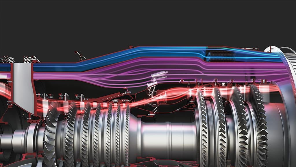
Details of the operating cycles of the new-generation adaptive engines remain sparse, but the key difference between the GE XA100/P&W XA101 and earlier variable-cycle concepts such as GE’s XF120 from the 1980s is the addition of the third air stream, which is external to both the core flow and standard bypass duct. Adaptive inlet devices, working in combination with a variable-area nozzle, modulate the flow in the third stream as well as the conventional bypass duct. The combined devices dynamically alter the fan pressure ratio and overall bypass ratio—the two key factors influencing specific fuel consumption and thrust.
- Third stream key to XA100
This contrasts with the XF120, also known as the GE37, which employed a double-bypass approach to vary the cycle using a series of fan bypass doors, core bypass ducts and a variable-area bypass injector (VABI) aft of the low-pressure turbine. When the engine was operating in turbofan mode, both the fan and core bypass were open and the VABI closed. The injector, which helped to match the fan-to-core pressure, provided cooling air to the exhaust liner.
When the engine was in turbojet mode, the fan bypass door was closed, and a smaller amount of air was discharged into the bypass through the core bypass duct. The fan supercharged the engine core, and the VABI, which was located upstream of the afterburner, was opened to reinject the remaining bypass stream into the throat of the exhaust.

Related Content


Comments
For current days, It seems so straight forward that a machine that can vary airflow, fan/compressor pressure ratios, bypass, thrust, etc. would include studies of the entire propulsion system with variable inlets as well as variable exhausts. Looking at the propulsion system matching options at each part of the total system, accounting for all throttle dependent losses (inlet/exhaust losses) as well as those of each of the internal components of the system in full up mission simulations would finally quantify the benefits of such a system.
It is noteworthy that one of the problems of an earlier variable cycle offering was a lack of quantitative definition of the systems value to the mission performances of a variable cycle engine in an aircraft propulsion system with fixed inlets. Such quantification was not possible for verifications in the aircraft and engine development testing environments.
In that era, comparisons of overall aircraft mission performances between variable cycle and conventional cycle afterburning turbofans consistently showed no significant advantages of the variable cycle. Perhaps worse was the perceived risk of the more complex variable cycle engine. These risks were perceived by the user, to pose significant effects to reliability, maintainability and logistics of the variable engine. Weighed against insignificant mission performances and a lack of test data addressing and quantifying the effects of cycle variation, the military took the perceived lower risk approach.
So one could hope for an Air Force funded effort to couple advanced propulsion system concepts with advanced hi performance aircraft concepts and do the hard work of sorting out the contributions of all the propulsion system components in finally assessing the systems value of variable propulsion technology.
The fact that one can manipulate the flow path of an advance turbofan has been known since the ATEGG experiments and demos of the early 1970's.
One might recall a simpler but illustrative example. There was great consternation across the development effort that led to the High Bypass Turbofans for the Air Force's C-5A Cargo Aircraft. The great concern dealt with how the big fan engine would integrate into the design without excessive losses. When some systems analyses/technical visibility finally evolved, the Air Force went forward with an engine that yielded great benefits to cargo aircraft systems for both military and commercial aircraft.
Maybe the key thing to remember lies in not having target fixation on flange to flange engine performance capabilities but to include a focus on installation alternatives as part of total propulsion system development. After all, variable flange to flange turbine engine concepts have been with us since the AMSA demonstrator days preceding the B-1 Bomber in the early 1970's. Some were actually tested using engine hardware of the day.